Durango Bill's
Dragon Curves
If you were to repeatedly fold a long strip
of paper from right to left, and then partially unfold it so
that each crease formed a right angle, what would the result
look like? Let's look at a computer generated version and see
what happens.Dragon Curves
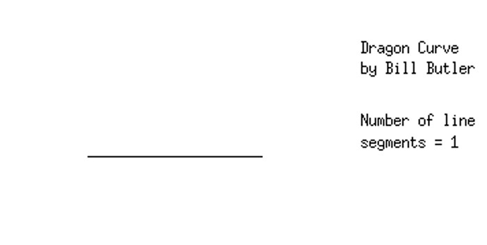
The first step to solve this problem is to start with a long strip of paper. In this illustration, we just draw a long straight line. The next step is to fold the line in half from right to left, and then partially unfold it to form a right angle.
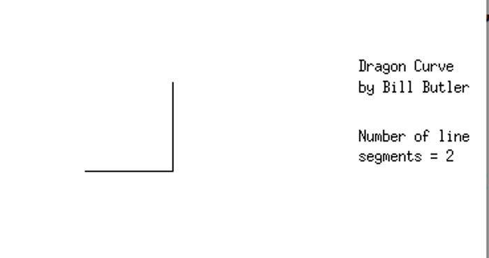
After a single fold from right to left and a partial unfolding, we have a single right angle. A couple items of note.
1) The folding operation has doubled the number of edges from 1 to 2.
2) An alternate way of looking at the transformation would be the following:
a) Mark the left end of the original line as the "Start Point"
b) Mark the right end as the "End Point"
c) Duplicate the original line with another line directly on top of it.
d) Rotate this duplicated line 90 degrees (a right angle) clockwise around the "End Point"
3) We now have the 2nd diagram.
The next picture repeats the above steps.
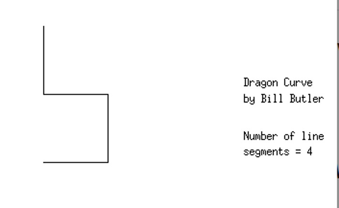
If we fold our strip of paper 2 times and then partially unfold it, we get the above diagram. Again, a second fold has doubled the number of line segments from 2 to 4. Also, if we duplicate the diagram illustrated in the previous picture, and rotate it 90 degrees clockwise around the end point in the upper right, we get the above result.
Folding a strip of paper additional times quickly becomes impossible due to the physical thickness of the paper, but computer representations of the process don't have this problem. This leads to the following "3-folds" and partially unfolded result.
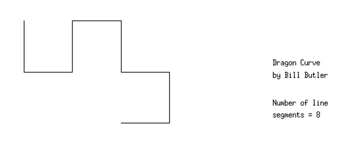
The picture above shows the result after 3 folds and partial unfolding. The number of line segments has again doubled. Also, the curve could be constructed by another 90 degree clockwise pivot around the end of the top line in the previous picture.
This pivot method could be used as a computer algorithm for generating the curve. The steps might be:
To generate the left and right turns for fold number "N + 1"
1) Execute all the turns for fold number "N"
2) Add a left turn
3) Do step 1) in reverse order and swap the words "Left" and "Right".
For example:
Construct the turn instructions for 1 fold:
Initially (0 folds) there are no turns for steps 1) and 3). Just add a left turn for operation 2). Thus the result for 1 fold is: Go straight, turn left, go straight. (For future stages we will ignore the "go straight" instructions.)
Construct the turn instructions for 2 folds:
1) The turn sequence for 1 fold was: Turn Left
2) Add a left turn
3) Do step 1) in reverse order and swap "Left" and "Right". For this round, 1) was "Turn Left". After the Left/Right swap we have "Turn Right".
Thus the turn instructions for 2 folds becomes:
1) Turn Left
2) Turn Left
3) Turn Right
Construct the turn instructions for 3 folds:
1) We have Left, Left, Right from the above 2 folds
2) Add a Left
3) Do step 1) in reverse order and swap the "lefts" and "rights". This becomes: Left, Right, Right
The entire sequence for 3 folds is thus: Left, Left, Right, Left, Left, Right, Right
There is an easier way to generate the sequence. In the above algorithm, you need all the turns for "N" folds stored in the computer's memory before you can calculate the turn sequence for "N + 1" folds. In practice, this isn't needed. Please see the computer code at the bottom of the page. The memory isn't needed and the code executes MUCH! faster. (e.g. It took a smallish fraction of a second to generate the 1,048,575 turns for 20 folds.)
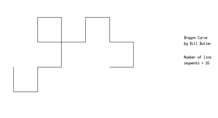
The result after 4 folds. Once again the number of line segments has doubled, and a 90 degree clockwise pivot could be used to generate this next stage.
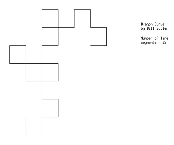
The result after 5 folds. Of interest to math fans, the number of line segments equals 2 raised to the number-of-folds power. The original starting point is a little above the center of the picture.
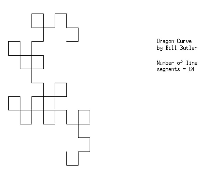
The result after 6 folds. We now have 26 = 64 line segments. The original starting point is in the upper left quadrant of the picture.
(Click on picture for a large image)
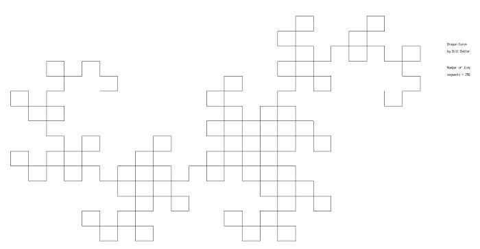
After 2 more folds (total of 8 folds), we now have 28 = 256 line segments. To make room for the larger number of line segments, the scale is being reduced. The original starting point is in the upper left quadrant.
(Click on image for a large version)
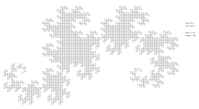
4 more folds increases their number to 12. The number of line segments is up to 212 = 4,096. Once again the scale has been reduce to accommodate the rapidly increasing size of the diagram. The original start point is now on the right side of the diagram.
(Click on image for a large version)
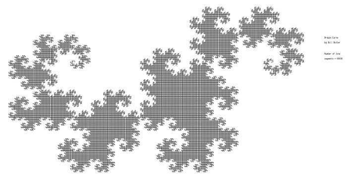
Another 4 folds and the number of line segments is up to 216 = 65,536. The original start point is now on the left side of the diagram. The rapidly increasing size of the diagram has forced the scale to be reduced to the point where line segments are barely discernible - even in the large version of the picture. On the other hand, the "dragon" patterns are becoming more recognizable.
(Click on image for a large version)
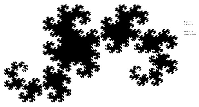
Another 4 folds and the number of line segments is up to 220 = 1,048,576. The individual line segments are no longer discernible with the result that the entire image is reduced to a solid black diagram. Offsetting this, the "dragon" is now showing its full shape.
If you want to keep track of the original starting point, it's now on the right side of the picture.
Numerically, the folding process could be continued indefinitely, but on a practical basis, it would be difficult to generate a worthwhile image. By now it should be apparent that the patterns form a fractal repetition with a repeat image similarity every 8 folds.
Another interesting item. If you take the above diagram (or any of the other sizes), make 3 more copies, respectively rotate these 3 images 90, 180, and 270 degrees about the original start point (either clockwise or counterclockwise), the whole center of the page (as measured from the start point) would be covered by the resulting diagram. Of interest, there would be no overlapping lines. The 3 additional images would exactly touch each other at their individual corner points. There would be no overlapping lines and no blank areas.
(Click on image for a large version)
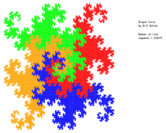
The picture above shows 4 interlocking Dragon Curves. The primary Dragon Curve is in blue while the red green, and orange curves show respective 90, 180,and 270 degree counterclockwise rotations around the center point.
Solution time for the 1,048,576 line segment display was a smallish fraction of a second using the computer code shown below. The diagram was drawn by a separate program ("gnuplot"), and gnuplot needed less than 1 second for the above diagram. ("gnuplot" is a multi-platform (Windows, Apple, Linux, etc.) program that can draw diagrams using the file output from any computer program that can write an output file.)
The Computer Code
The following computer code (in "C") to generate a dragon curve is deceptively simple. The code (below) is an exact copy of the working portion of the actual code that produced the black and white illustrations on this web page.
The code that does all the calculation work for the turns starts with "LocLowestBit =" and ends with "dir &= 3". It could be easily reduced to 1 line, but the expanded version is shown for clarity.
// Global Variables
int NewXcoord, OldXcoord, NewYcoord, OldYcoord;
int length, NbrLines; // Nbr. of line segments to draw and their length // "NbrLines" can be any positive integer.
int main() {
int dir = 0; // Which way to go. Right, Up, Left, Down.
int LocLowestBit; // Location of lowest set bit in "Count"
int Count; // Number of line segment
InitSys(); // Get user info. Init Xmove[],Ymove[], etc.
// Value of "dir" Graph move
// 0 Right
// 1 Up
// 2 Left
// 3 Down
// Open the output file (used by gnuplot)
file1 = fopen("/home/bill/LinuxVerOfWin7/Temp/gnuplotedges.txt", "w");
for (Count = 1; Count <= NbrLines; Count++) { // For each line segment to be drawn
OldXcoord = NewXcoord; // One end point for line to draw
OldYcoord = NewYcoord;
NewXcoord = OldXcoord + Xmove[dir]; // Other end of line to draw
NewYcoord = OldYcoord + Ymove[dir];
// Write coords to file for gnuplot
fprintf(file1, "%6d %6d\n", OldXcoord, OldYcoord);
fprintf(file1, "%6d %6d\n\n", NewXcoord, NewYcoord);
// Set-up for next line segment
LocLowestBit = ffs(Count); // "Find First Set" bit
// (starting from lowest bit)
if (Count & (1 << LocLowestBit)) // Calculate directional index
dir--; // ("1 << LocLowestBit" means 2^LLB)
else // (dir-- results in turn right)
dir++; // (dir++ results in turn left)
dir &= 3; // Just use lowest 2 bits
}
fclose(file1); // All line segments are in the file.
GnuplotCmds(); // Creates a text/script file
// for input to gnuplot.
// Display instructions to user.
puts("\nTo display the Dragon Curve . . . (assumes that you are in default library \"Bill\")\n");
puts("1) Click on the \"Terminal\" icon to start a terminal session.\n");
puts("2a) Key in: gnuplot \"gnuplotcmds.txt\"");
puts(" Press: Enter");
puts(" or");
puts("2b) Key in: gnuplot");
puts(" Press: Enter");
puts(" Key in: load \"gnuplotcmds.txt\"");
puts(" Press: Enter\n");
PauseMsg(); // Pause program. Let user read screen.
return 0;
}
Web page generated via Sea Monkey's Composer HTML editor
within a Linux Cinnamon Mint 18 operating system.
(Goodbye Microsoft)
Return to Durango Bill's home page
